How Fin Spacing Affects Heat Transfer and Pressure Drop in Finned Tube Heat Exchangers
How Fin Spacing Affects Heat Transfer and Pressure Drop in Finned Tube Heat Exchangers
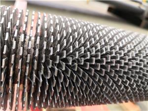
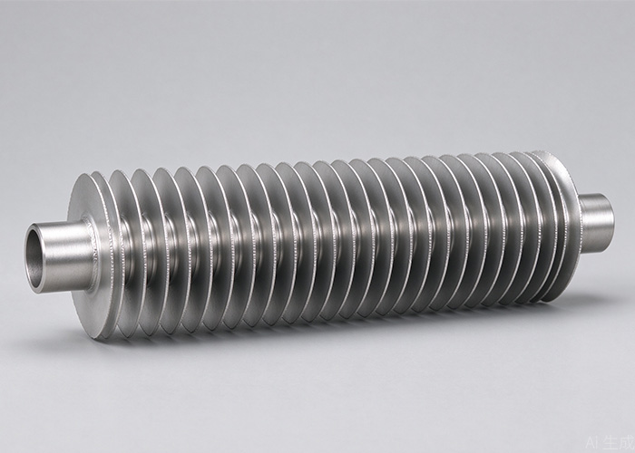
Fin spacing is one of the most influential geometric parameters in a finned tube heat exchanger. It affects how much heat-transfer surface can be installed in a given volume, how easily air or gas can move between the fins, and how much pressure drop the fan or blower must overcome.
The relationship is not simply “smaller spacing means higher efficiency.” Tighter spacing increases the available fin area, but it can also restrict airflow, increase pressure drop, and encourage fouling. Wider spacing improves airflow and reduces resistance, but reduces the amount of fin surface available for heat transfer.
Recent numerical research confirms this trade-off. A 2026 study found that changing fin spacing significantly affected both heat transfer and pressure drop, with the best configuration depending on the overall fin geometry and tube arrangement.
For engineers and buyers, the practical objective is therefore to find a spacing that balances heat-transfer capacity, airflow resistance, fouling risk, fan power, and operating conditions.
How Does Fin Spacing Affect Heat Transfer?
The basic question is whether reducing the distance between fins always improves a heat exchanger's performance.
It does not.
Finned tube heat exchanger efficiency depends on the interaction between heat-transfer area and airflow. When fins are placed closer together, more fin surface can fit around the tubes. This can increase the potential for heat transfer.
However, the smaller flow passages also create greater resistance to the moving air or gas.
Research on annular-finned tube bundles shows that decreasing fin spacing generally increases the air-side heat-transfer coefficient while also increasing pressure drop. The effect is strongly influenced by the boundary layer developing between adjacent fins.
This creates a practical trade-off:
1. Smaller fin spacing
More heat-transfer area
Higher air-side heat-transfer coefficient
Higher pressure drop
Greater potential for dust or fouling accumulation
2. Larger fin spacing
Better airflow passage
Lower pressure drop
Easier cleaning
Less heat-transfer area per unit volume
A numerical study of annular-finned tubes found that fin spacing and fin height had a stronger influence on performance than fin thickness under the investigated conditions. It also found that the sensitivity of heat transfer decreases as spacing becomes sufficiently large.
This explains why finned tube fin spacing should not be selected independently.
Tube diameter, fin height, fin thickness, tube arrangement, air velocity and fluid properties all influence the result.
For an industrial heat exchanger, the correct design question is therefore not “How close can we place the fins?” but rather:
How much heat transfer is required at an acceptable pressure drop and operating cost?
That distinction is particularly important for air-cooled heat exchangers, economizers, waste-heat recovery equipment and other systems where the air side represents a significant portion of the total thermal resistance.
What Is the Optimal Fin Spacing for a Heat Exchanger?
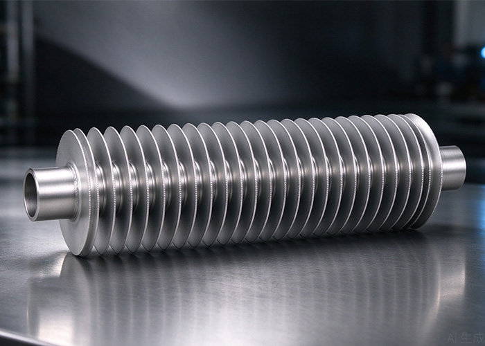
There is no universal value for optimal fin spacing for heat exchangers.
The appropriate spacing depends on the operating environment and the geometry of the complete heat exchanger.
For example, tighter spacing can make sense when:
Air is relatively clean
Space is limited
High heat-transfer density is required
Fan capacity can accommodate additional pressure drop
Fouling is not a major concern
Wider spacing may be preferable when:
Air contains dust or particulates
The exchanger operates outdoors
Regular cleaning is required
Fan power is limited
Pressure drop is a major design constraint
A useful way to think about heat exchanger fin spacing is as a balance between thermal performance and hydraulic performance.
Recent research illustrates why a single “best” spacing cannot be applied to every exchanger. A 2026 CFD optimization study found different optimum fin spacing values for inline and staggered configurations. In its investigated cases, the optimized inline design used 4 mm spacing, while the optimized staggered design used 6 mm. These values belong to those specific geometries and operating conditions rather than representing a general industry standard.
Another study found that increasing fin pitch from 1.2 mm to 1.8 mm reduced heat-transfer rate by 9.4% but increased energy-efficiency ratio by 35%, because the reduction in air-side pressure drop outweighed the loss in heat transfer for that particular system.
This is a useful lesson for equipment designers.
How Should Buyers Specify Fin Spacing for a Finned Tube Heat Exchanger?
The final decision should be based on the complete thermal and mechanical design rather than a standard fin-spacing number.
When reviewing a supplier's proposal, check these parameters together:
Thermal requirements
Required heat-transfer capacity
Hot and cold fluid temperatures
Air or gas flow rate
Target outlet temperature
Heat-transfer coefficient
Allowable temperature approach
Fin geometry
Fin spacing
Fin height
Fin thickness
Fin material
Fin type
Tube diameter
Tube pitch
Flow requirements
Air-side velocity
Pressure drop
Fan or blower capacity
Flow distribution
Tube arrangement
Operating environment
Dust concentration
Moisture
Corrosive gases
Fouling tendency
Cleaning method
Outdoor exposure
These factors matter because finned tube heat exchanger efficiency is determined by the complete thermal-hydraulic system.
A supplier should be able to explain why the proposed finned tube fin spacing fits the specified duty rather than simply offering the most common pitch.
Common mistakes
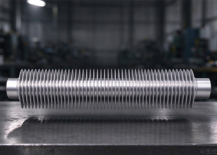
Choosing the smallest possible spacing
More fins do not automatically mean better overall performance. Excessive resistance can increase fan power and reduce effective airflow.
Better approach: optimize heat transfer and pressure drop together.
Using the same spacing for every application
Clean HVAC air and dusty industrial gas have very different requirements.
Better approach: consider fouling and cleaning conditions during design.
Ignoring tube arrangement
Inline and staggered tube arrangements change flow behavior around the fins. Research shows that their response to spacing can differ significantly.
Better approach: evaluate fin spacing with tube layout and air velocity.
Looking only at initial efficiency
A compact exchanger may perform well when new but lose performance quickly if dust blocks narrow passages.
Better approach: consider lifecycle performance and maintenance.
Specifying fin spacing without allowable pressure drop
A thermal design that cannot operate within the available fan power is not an efficient design.
Better approach: include both thermal duty and maximum pressure drop in the RFQ.
How BEILAI can fit into the sourcing process
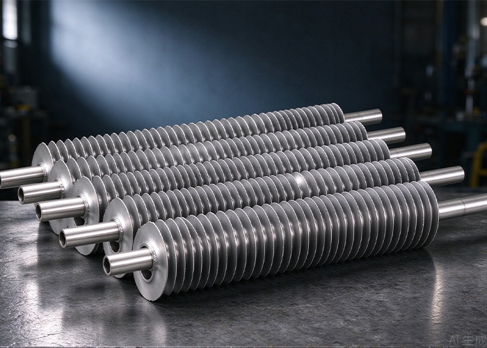
For projects requiring finned-tube components, the tube itself is only one part of the final heat exchanger.
BEILAI's tube portfolio covers applications including heat exchangers, boilers, energy equipment and other industrial systems.
For an OEM or project procurement requirement, buyers can provide:
Tube material
Tube OD and wall thickness
Fin material
Fin spacing
Fin height
Fin thickness
Tube length
Operating temperature
Pressure
Required heat-transfer duty
Applicable standard
This gives the manufacturer enough information to evaluate the tube and fin configuration against the actual application.
For large industrial heat exchangers, it is also useful to confirm dimensional tolerances, material certificates, surface condition and inspection requirements before production.
BEILAI can therefore be considered as part of the sourcing process where the project requires specified tube materials and dimensions rather than a generic off-the-shelf tube.
FAQ
Does smaller fin spacing always improve heat transfer?
No. Smaller spacing generally provides more surface area and can increase heat transfer, but it also increases airflow resistance and pressure drop. The optimum depends on fin geometry, air velocity, tube arrangement and operating conditions.
What is fin spacing in a heat exchanger?
It is the distance between adjacent fins. It determines the size of the air or gas passages through the finned section and directly affects available surface area, flow resistance and fouling behavior.
How does fin spacing affect pressure drop?
Reducing spacing makes the flow passages narrower, which generally increases friction and pressure drop. Increasing spacing usually reduces pressure drop but also reduces heat-transfer surface density.
What is the optimal fin spacing for heat exchangers?
There is no universal optimum. The correct value depends on heat-transfer duty, airflow, pressure-drop limits, fin geometry, tube arrangement and fouling conditions. Recent optimization research has produced different optimum values for different exchanger configurations.
Should dusty applications use wider fin spacing?
Often, yes. Wider passages can reduce the tendency for dust and particles to accumulate between fins and can make cleaning easier. However, the final design still needs to meet the required heat-transfer duty and pressure-drop limits.